Eutectic die bonding
Eutectic die bonding, sometimes referred to as eutectic die attach, is a die bonding technique used for devices that require enhanced heat dissipation, such as high-power amplifiers. The technique is also used when the outgassing of traditional die bonding epoxies is of concern. Gold-tin, gold-germanium, and gold-silicon are three common eutectic alloys. In simple terms, the eutectic die bonding process is automated by placing the package or substrate on, or moving it to, a surface that can be thermally controlled. The automated system then sequentially places the solder preform and a die onto the substrate. The temperature is then ramped up to achieve reflow. Ideally, temperature ramps are performed quickly for throughput and quality reasons. The process must occur in an inert environment to avoid oxidation. A void-free bond is obtained by using a technique called scrubbing. Below we outline the details of the eutectic die bonding process including an automated system using an in-line method of processing multiple parts simultaneously.
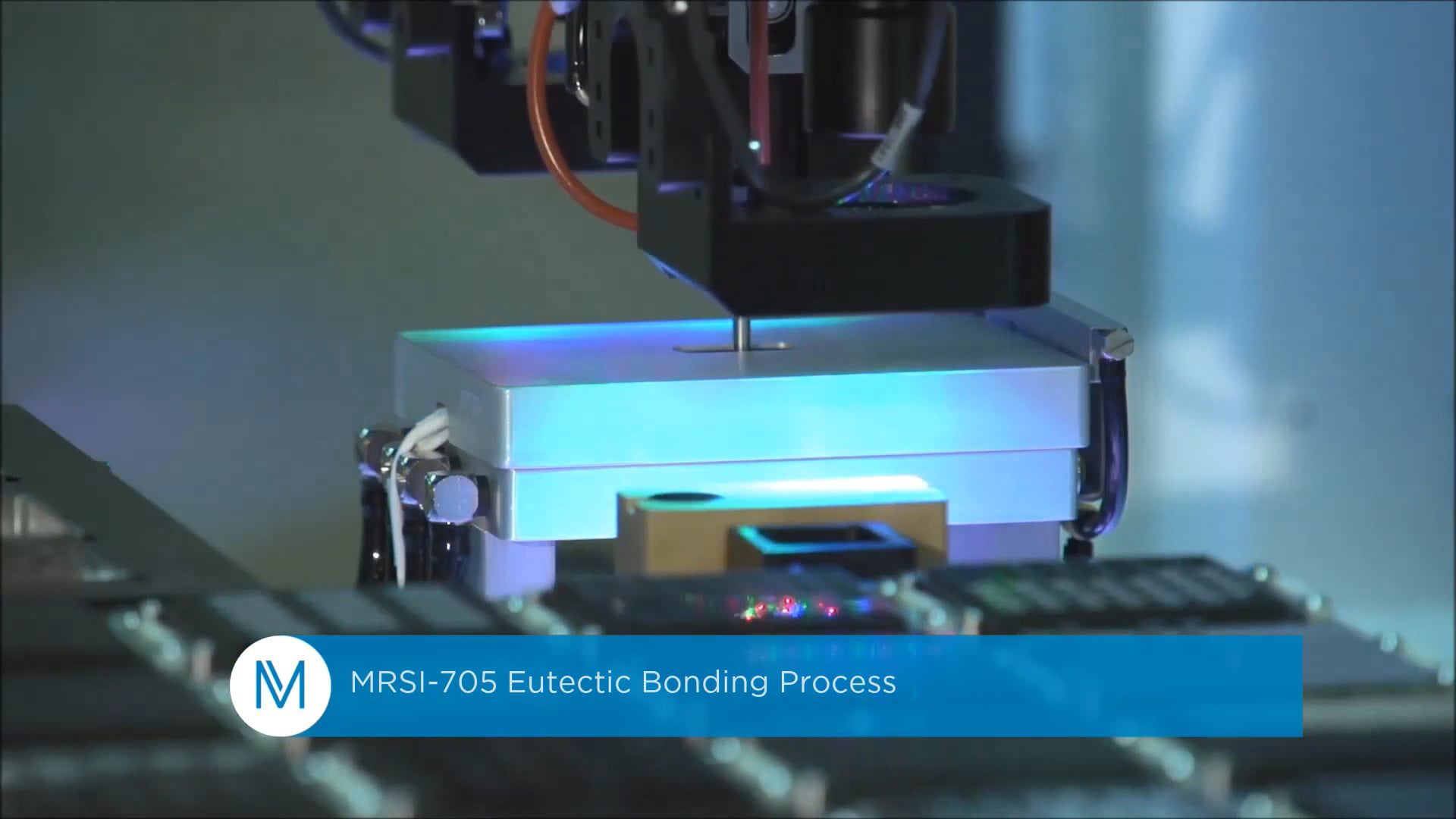
MRSI-705 Eutectic Bonding Process
Solder Reflow Eutectic Bonding
Eutectic bonding is defined as the process of using an intermediate solder alloy to form a continuous bond between two surfaces. Eutectic bonding is a die bonding technique, used primarily to produce hermetically sealed packages that are sensitive to outgassing of standard die attach materials. In optoelectronics applications for example, this often means two gold-plated surfaces being joined by lead-tin, gold-tin or gold-germanium solder. To achieve this bond, it is typical for a solder preform to be placed on one component, usually a carrier or submount; the second component, often a microwave device, a photodetector or a laser chip, then interfaces to the preform. The temperature of the assembly is brought up to just above the melting point of the solder by either heating the base on which the assembly rests, or by flowing heated gas over the assembly. Just as the solder liquifies, the chip is placed with controlled force. The part is cooled to below the reflow temperature and the eutectic bonding is complete. Depending upon the device type and construction, scrubbing may be used during the placement process. A eutectic composition is used so that the eutectic bonding process temperature is minimized, as shown in Figure 1.
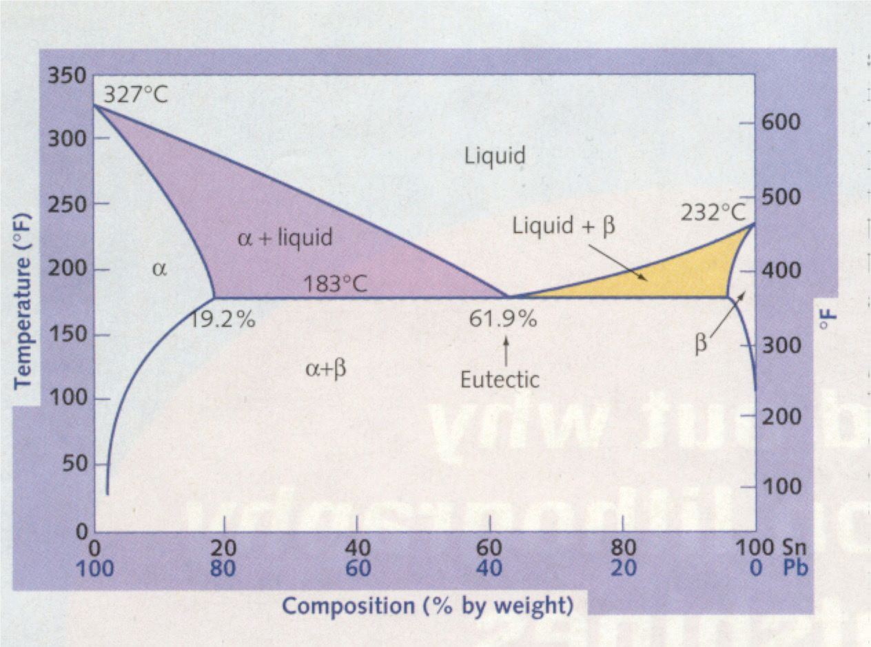
Figure 1: Eutectic transitions for a given metal composition-in this case, tin-lead
Scrubbing
The scrubbing step consists of applying both vertical and lateral forces to a device during its placement to a substrate. The chip is usually moved three to five mils (0.003”-0.005”) in the negative, followed by a similar but positive move in the x or y direction; this is repeated for several cycles. Movement in alternate directions is also possible. Rotational scrubs are sometimes employed. Scrub parameters consist of amplitude, speed, and frequency in the x, y, and theta directions. Parameters are determined by process requirements such as the surface area of the chip or the mass of the carrier and process constraints such as proximity to adjacent die. Scrubbing is a critical process step in the formation of a common material (bond) among the three materials. Forcing out air reduces voiding. Also, the solder is better distributed across the die, and the pressure assists the diffusion process.

Cover Gas
During the time that the part is subjected to heat, it is important to control the gas atmosphere in which the soldering process occurs. Eutectic bonding is usually performed in an inert environment to prevent oxidation of the bonding surfaces. A 90-95% nitrogen-hydrogen mix can be used so that hydrogen is present for use in the formation of the bond (Figure 2).
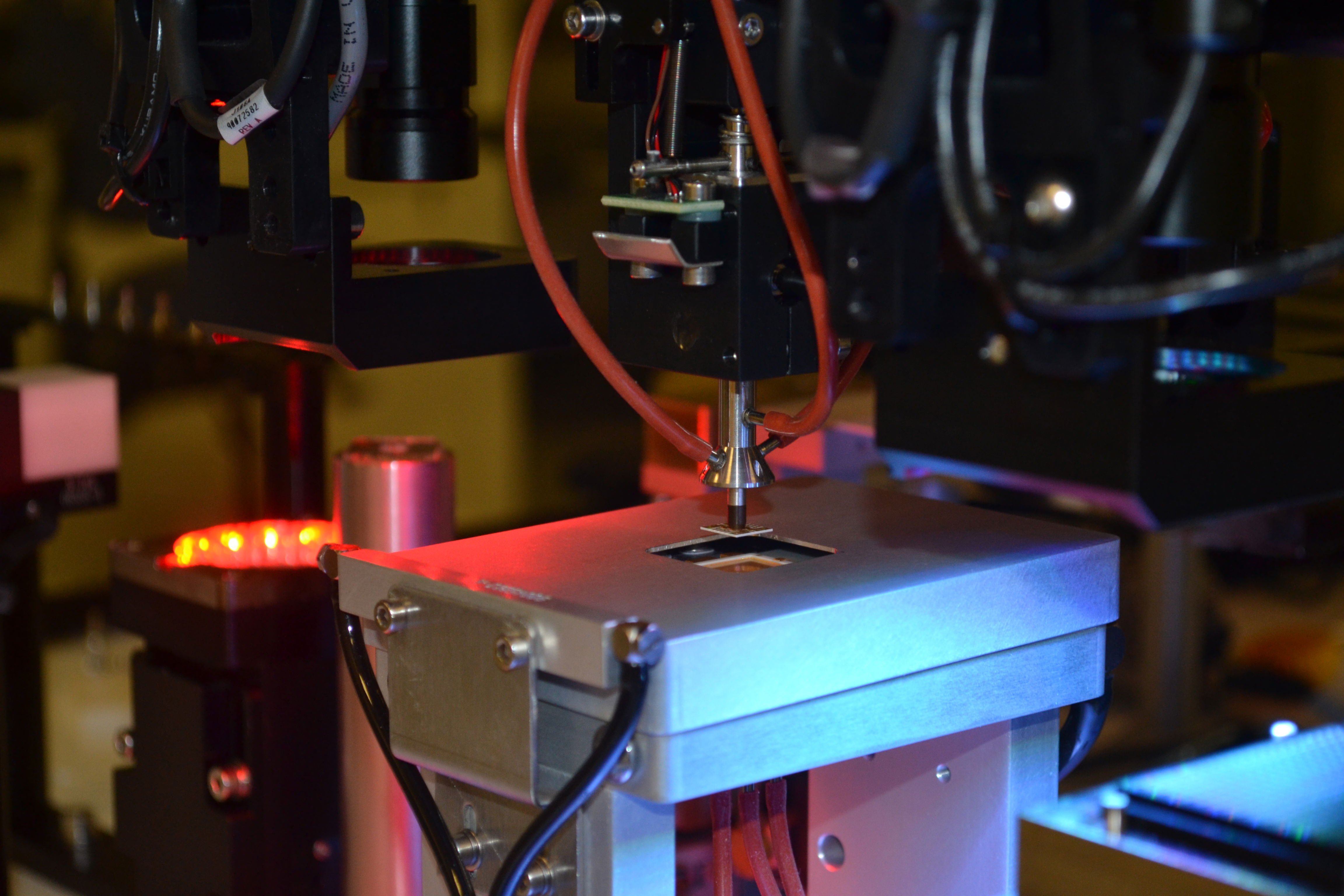
Figure 2 : A Pulse-heated, fast-ramp eutectic stage
Fully Automated, In-line Eutectic Bonding Process
From the perspective of the equipment manufacturer, control of the eutectic bonding process involves several key elements and processes. These include: the ability to accurately control the temperature of the device, to accurately control contact forces, to precisely control the scrubbing action used to break through oxides, to introduce energy to spike the temperature and to mix the various metals contained in the solder, to provide an inert atmosphere with cover gas or a fluxing agent with cover gas, and to control cooling and collets. The material set used in the eutectic die bonding process will determine the temperature used for eutectic die bonding.
In-line eutectic die bonding provides a means to achieve high production volume. By utilizing a progressive hot plate system that indexes through heat zones, eutectic die attach can be performed on parts transported in “boats” or carriers that are loaded, processed, and unloaded to cassettes automatically. Strict temperature control is achieved by indexing parts through pre-heat, assembly, and post-heat zones. Temperature profiling of each heat zone enables fast processing of parts that have a high thermal mass. High throughput is achieved by limiting the temperature ramping time at the eutectic die bonding station. All temperature zones are under a cover gas consisting of a nitrogen and hydrogen mix, used to prevent oxidation of the heated parts (Figure 3).
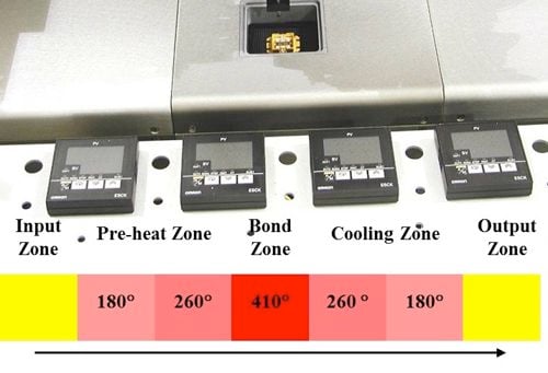
Figure 3: In-line eutectic bonding under cover gas
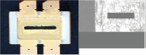
Figure 4: Eutectic package (left) with Sonoscan inspection results (right)
For gold-silicon eutectic, an automated vision system registers the package. The machine then picks and places the die, using a scrubbing action (as previously described) to facilitate the formation of the eutectic bonding. A heated cover gas of hydrogen and nitrogen is typically present over the eutectic bonding area.
For solder-reflow eutectic bonding, such as gold-tin (Au/Sn) attachment of gallium arsenide (GaAs) and gallium nitride (GaN) dies, the system aligns the package, then picks and places a preform onto the heated package (if required, the preform can be pre-deposited) (Figure 4). To enable reflow, the die is picked and placed at its desired placement location and scrubbed, while the temperature at the eutectic die bonding position is ramped using a pulse heated eutectic bonding stage.
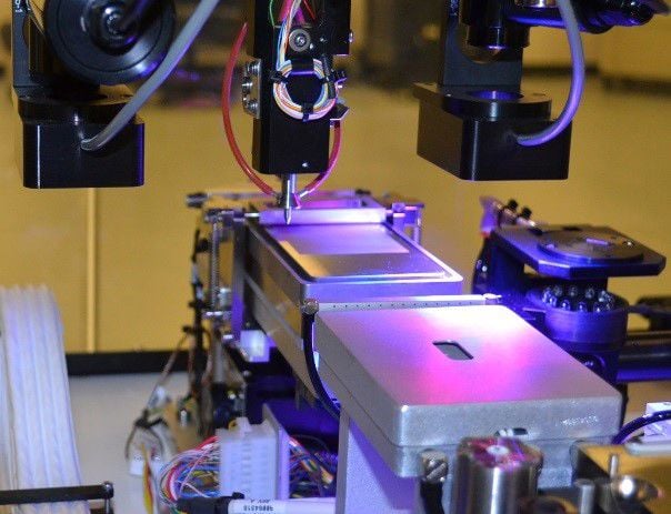
Standalone Eutectic Die Bonding
Finally, the boat is indexed to the next substrate position and the above process is repeated until all the boat positions have been bonded. As the indexer transfers the boat, the parts are incrementally cooled by passing over a cool down zone. When completed, the indexing conveyor transfers the boat to an output magazine loader.
Watch the Eutectic Bonding Video.
